

Uncovering the truth about inrush currents
Lights are flickering, protection devices are tripping for no apparent reason and IT equipment is randomly malfunctioning. What’s going on? There can be many reasons for problems like these, but one that’s surprisingly common yet often overlooked is inrush currents. What exactly are inrush currents, why do they cause problems, and how can they be measured?
When we think about loads – motors, lights, IT equipment and so on – connected to an electrical installation, our primary concern is often with the current that the load draws from the installation. “That motor will draw about 30 A”, “Those lights will take about 2 A”, and so on. But these are steady-state currents and, important as they are, they don’t tell the whole story. That’s because many types of load don’t draw their steady-state current from the moment they’re switched on. Before they settle into the steady-state condition, they draw a much larger current for a relatively short period of time. This is the inrush current.
For example, when a motor is energised using an ordinary electromagnetic starter, it can draw an inrush current that’s up to 10 times its normal running current. And, particularly if the motor is heavily loaded, it can take several seconds for the current to settle back to the steady-state value. Transformers draw even higher inrush currents at switch on – up to 25 times their normal rated current. Even switch-mode power supplies, which these days are used in everything from computers to LED lighting systems, often draw surprisingly large inrush currents. In other words, loads that draw inrush currents are everywhere!
Why does this matter? Problems resulting from inrush currents can be divided into two categories. The first involves circuit protection equipment, such as circuit breakers and fuses. The purpose of these is to trip (or blow) if they are subjected to a higher than normal current. Unfortunately, an inrush current is a higher than normal current, so it can often be difficult to select protection equipment such that it adequately protects the installation but doesn’t trip when a motor starts or a transformer is energised.
The second category of problem involves voltage dips. If you draw current from an electrical installation, the voltage supplied to the loads connected to that installation will inevitably fall. This is thanks to Ohm’s law, the impedance of the cables and other factors like the impedance of the transformer feeding the installation. It stands to reason, therefore, that if you draw a large inrush current, the voltage drop will be higher than in steady-state operating conditions.

This sudden reduction in supply voltage may just make the lights flicker, which is annoying but not necessarily disruptive, or it may adversely affect the operation of computers and other electronic equipment, which is likely to be much more problematic.There are two key takeaways from this discussion: inrush currents are everywhere, and they can be a source of trouble. What’s to be done? Well, the first step, as always, is to gather reliable and accurate data about what’s really going on, and that means making measurements of the inrush currents in your installation. But before you do this, there’s something you need know: most instruments that claim to offer inrush measuring capabilities don’t provide the full picture.
The problem with these instruments is that they can only measure inrush from a ‘standing start’ – in other words, in a system that is initially powered off. This can be very inconvenient, and in most cases, it isn’t a true representation of what happens in real life, where a load that produces an inrush current is most likely to be connected to an installation that’s already live. To address this limitation, we are now offering instruments with a True InRush® function. As easy and convenient to use as ordinary clamp meters, these instruments can measure the initial inrush current when a specific load is connected to the installation, whether or not the installation was already powered, and can also measure subsequent inrush events caused by connecting further loads to the installation.
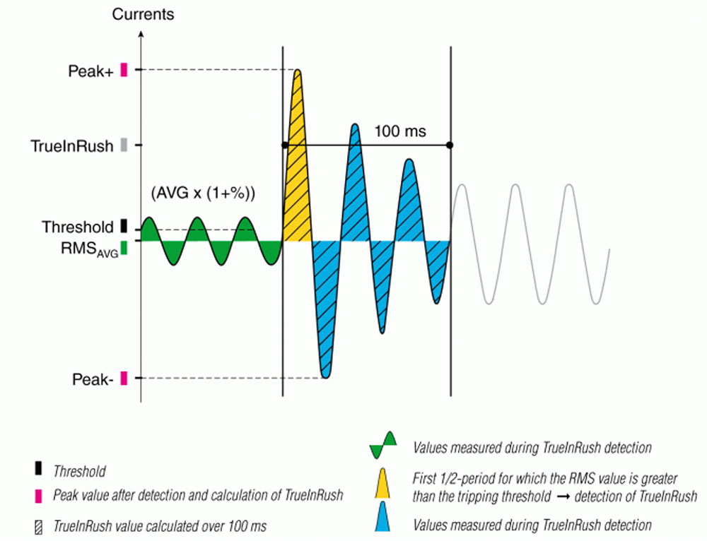
To deliver this functionality the instruments use a novel measurement algorithm. First, this captures the steady-state current for the installation, which it filters to remove anticipated normal variations, producing an RMS reference current. Then it carries out half-period monitoring, calculating the equivalent RMS current for every half cycle of the supply. If this exceeds a user-defined threshold, which is an indication that an inrush event has occurred, the instrument starts making measurements every millisecond, and this continues for a total time of 100 ms. At the end of this time, the results are processed digitally to calculate the true inrush current for the period. Figure 1 gives an overview of this procedure.
The accurate and realistic inrush data provided by these new instruments puts you in a position to easily identify any problem areas of your installation, and also any problem loads. Once these issues have been identified, remedial measures can be put in place. These are outside the scope of this article, but could, for example, include installing a soft starter or a variable speed drive to control a motor rather than using a conventional electromagnetic starter, or upgrading protection devices so that they are no longer prone to tripping by the inrush currents, but still provide a satisfactory protection function.
When the appropriate remedial actions have been taken, the final step is to confirm that all is now well by repeating the inrush measurements. In fact, it is advisable to routinely repeat the measurements, along with other key power quality measurements, at regular intervals to ensure that the performance of the installation is always optimised, and to provide warnings of any developing problems.